Phase-Shifting Rectifier Transformer for Industrial DC Power Systems: A Buyer’s Guide

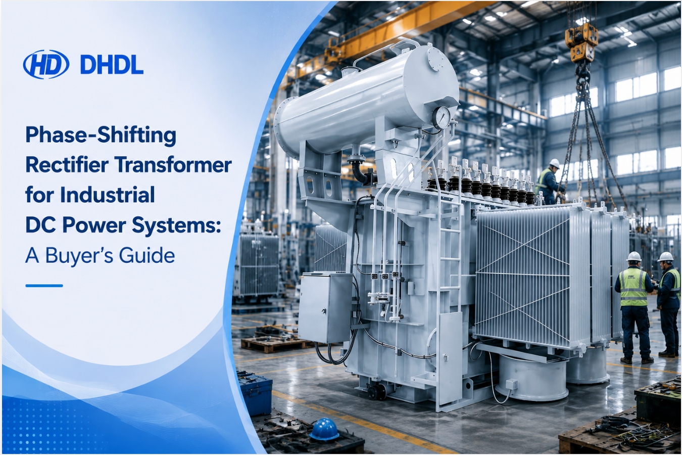
Industrial DC power systems do not place the same demands on a transformer as conventional building or utility distribution systems.
In a conventional installation, a transformer mainly changes one AC voltage level to another. In an industrial rectifier system, however, the transformer must also coordinate with the rectifier arrangement, connected process load, harmonic requirements, voltage regulation, cooling conditions, and protection system.
Therefore, buyers should not select a phase-shifting rectifier transformer by comparing capacity and voltage alone.
The DHDL phase-shifting rectifier transformer for industrial DC power systems is intended for industrial power-conversion applications that require transformer and rectifier coordination.
From a user’s perspective, the main question is not simply whether the transformer can energize the rectifier. More importantly, you need to determine whether the transformer can support the required DC output, phase-shifting arrangement, load profile, power-quality objectives, and operating environment as part of one complete system.
This guide explains how to evaluate that decision.
What Is a Phase-Shifting Rectifier Transformer?
A phase-shifting rectifier transformer supplies controlled AC voltages to one or more rectifier sections. The rectifier system then converts these AC outputs into the DC power required by the industrial process.
Unlike a standard distribution transformer, a phase-shifting rectifier transformer may use specially arranged secondary windings to provide outputs with defined phase relationships.
As a result, the transformer can support a multi-pulse rectifier configuration when the overall system requires it.
In general, this arrangement may help an appropriately engineered rectifier system:
- Supply the required voltage to different rectifier bridges
- Coordinate multiple rectifier sections
- Improve the input-current waveform
- Reduce selected characteristic harmonics
- Support industrial DC voltage and current requirements
- Provide electrical isolation between the incoming network and rectifier equipment
However, these results depend on the complete transformer–rectifier design. Consequently, buyers should not treat “phase shifting” as a stand-alone performance guarantee.
The pulse configuration, phase displacement, winding arrangement, rectifier topology, network impedance, load characteristics, and system controls must work together.
Why Industrial DC Power Users Need a Special Transformer
Industrial DC processes can operate with high current, continuous duty, rapid load changes, or nonlinear rectifier loads. Therefore, the transformer must handle a different electrical duty from a conventional distribution transformer.
Depending on the project, an industrial DC power system may support processes or equipment such as:
- Industrial rectifier installations
- Electrochemical processing systems
- Electrolysis equipment
- Metal refining or surface-treatment systems
- DC furnaces or heating processes
- High-power DC drives
- Industrial charging systems
- Other production lines that require controlled DC power
These are general examples of industrial DC loads. Before selecting the product, buyers should ask DHDL to confirm suitability for the exact process and rectifier topology.
The Rectifier Creates a Nonlinear Load
A rectifier does not draw current in the same way as a simple linear AC load. Instead, its switching or conduction pattern can distort the current waveform.
Consequently, the transformer design may need to consider:
- Harmonic current
- Additional winding and structural losses
- Thermal stress
- Voltage distortion
- Rectifier commutation
- Load-current waveform
- Unequal secondary loading
- Short-duration overloads
- DC components under abnormal conditions
Therefore, selecting a standard transformer and connecting it to a rectifier without system analysis can create performance and temperature-rise risks.
The DC Process Determines the Required AC Design
Users often start a quotation request with the incoming AC voltage. However, the industrial process usually defines the more important operating requirement: the necessary DC voltage and DC current.
The rectifier supplier then determines the required AC input for the selected rectifier topology. After that, the transformer manufacturer can engineer the secondary voltages, winding arrangement, phase displacement, impedance, and insulation system.
In other words, the transformer specification should work backward from the process requirement instead of forward from a standard transformer catalogue.
The Transformer and Rectifier Must Be Engineered as One System
A phase-shifting rectifier transformer cannot deliver the intended system performance by itself. Instead, it must coordinate with the rectifier bridges and the connected DC load.
| System item | Information to confirm | Why it matters |
|---|---|---|
| Required DC output | Rated DC voltage and current | Defines the process-power requirement |
| Rectifier topology | Bridge arrangement and control method | Influences the required transformer outputs |
| Pulse configuration | Project-required pulse number | Affects the phase-shifting and secondary-winding arrangement |
| Phase displacement | Required angle between secondary outputs | Must match the rectifier design |
| Secondary voltage | Required AC voltage for each bridge | Determines whether the rectifier can produce the target DC output |
| Secondary current | Current required by each rectifier section | Affects winding and terminal design |
| Load profile | Continuous, intermittent, cyclic, or fluctuating duty | Influences thermal and capacity selection |
| Network data | Supply voltage, frequency, fault level, and permitted distortion | Supports insulation, impedance, and power-quality evaluation |
| Cooling conditions | Ambient temperature, ventilation, and installation arrangement | Affects temperature rise and long-term operation |
| Protection system | Upstream, transformer, rectifier, and DC-side protection | Ensures coordinated fault response |
If one party changes the rectifier topology after the transformer design has been approved, the transformer may no longer match the system. Therefore, control technical revisions carefully and require written approval from all relevant parties.
Phase-Shifting Rectifier Transformer vs. Standard Distribution Transformer
Although both products transform voltage, they serve different operating duties.
| Comparison factor | Phase-shifting rectifier transformer | Standard distribution transformer |
| Primary purpose | Supplies and coordinates with an industrial rectifier system | Supplies general AC distribution loads |
| Load type | Nonlinear rectifier load | General commercial, utility, or industrial AC load |
| Secondary arrangement | May require multiple coordinated secondary windings | Commonly uses a standard secondary arrangement |
| Phase relationship | May provide defined phase displacement between outputs | Usually does not provide a special rectifier phase-shifting arrangement |
| Design starting point | DC process, rectifier topology, and power-quality requirements | AC load capacity and distribution voltage |
| Harmonic consideration | Must consider rectifier-related harmonic duty | Evaluated for conventional distribution duty |
| Impedance coordination | Must coordinate with rectifier performance, fault current, and commutation | Selected mainly for distribution-system requirements |
| Terminal arrangement | May require several high-current connections to rectifier sections | Usually uses conventional HV and LV terminals |
| Thermal evaluation | Must consider nonlinear current and load profile | Generally based on conventional AC loading |
| Custom engineering | Usually project-specific | Often available in standardized ranges |
Therefore, using a standard distribution-transformer quotation as a price benchmark can be misleading. Even when the rated kVA appears similar, the winding complexity, terminal arrangement, thermal duty, testing, and engineering work may differ substantially.
What Benefits Should a Buyer Expect?
Buyers should connect every claimed benefit to a measurable project requirement.
Better Coordination with Multi-Pulse Rectification
When the project uses a multi-pulse rectifier arrangement, the transformer can provide secondary outputs with the required phase relationship.
As a result, the complete system can combine the rectifier outputs according to its intended topology.
However, the buyer must still verify:
- Pulse number
- Phase-shift angle
- Number of secondary windings
- Secondary-voltage balance
- Rectifier bridge arrangement
- Permitted phase-angle tolerance
Harmonic Management
Phase-shifting arrangements can help cancel or reduce selected characteristic harmonics in a properly designed multi-pulse rectifier system.
Nevertheless, buyers should avoid accepting a general statement such as “low harmonics” without supporting system data.
Instead, request:
- Defined harmonic targets
- Point of measurement
- Network conditions used for calculation
- Expected load range
- Rectifier topology
- Transformer impedance assumptions
- Harmonic study or calculation, if required
- Acceptance method after commissioning
More importantly, confirm whether the harmonic commitment applies to the transformer, rectifier package, or complete plant connection point.
Electrical Isolation
The transformer can provide separation between the incoming AC network and the rectifier side, depending on the selected design.
Therefore, the project engineer should define:
- Insulation level
- Earthing arrangement
- Electrostatic shielding requirement
- Surge environment
- Protection concept
- Permitted common-mode disturbance
Voltage Matching
The transformer provides the AC secondary voltage required by the rectifier to produce the target DC output.
However, nominal secondary voltage alone may not be enough. The design should also consider:
- Input-voltage variation
- Transformer regulation
- Rectifier voltage drop
- Commutation effects
- Cable voltage drop
- Required DC operating range
- Tap requirements
- Minimum and maximum process load
Reliable Continuous-Duty Operation
Many industrial DC processes operate for long periods and may have a high cost of unplanned shutdown.
Consequently, buyers should evaluate:
- Continuous load
- Peak load
- Overload cycle
- Ambient temperature
- Cooling conditions
- Harmonic heating
- Maintenance access
- Temperature monitoring
- Critical spare parts
The correct design should reflect the actual operating cycle rather than only the nominal rating.
Technical Information Buyers Should Confirm
The target product page identifies the equipment as a phase-shifting rectifier transformer for industrial DC power systems. Nevertheless, the final specification must match the individual project.
The following table can support the technical review.
| Parameter | Buyer’s question |
| Rated capacity | Does the rating cover the actual rectifier duty and operating cycle? |
| Primary voltage | Does it match the plant supply under minimum and maximum operating conditions? |
| Secondary voltage | Does each output match the rectifier bridge requirement? |
| Frequency | Is the unit designed for the project’s 50Hz or 60Hz system? |
| Number of phases | Does it match the incoming system and rectifier topology? |
| Pulse configuration | Which pulse arrangement does the complete system require? |
| Phase displacement | What angle is required between the secondary outputs? |
| Number of secondary windings | Does it match the number of rectifier sections? |
| Vector group | Does it match the system design and earthing arrangement? |
| Tap range | Is voltage adjustment required for network or process variation? |
| Short-circuit impedance | Does it support the required fault-current and rectifier performance? |
| Insulation level | Does it match the network voltage and applicable standard? |
| Cooling method | Is it suitable for the site environment and load profile? |
| Temperature rise | Has the design considered harmonic and continuous-duty heating? |
| Winding material | What material does the approved design specify? |
| Enclosure | Does it match indoor, outdoor, dust, humidity, or corrosion conditions? |
| Terminal arrangement | Can the transformer connect directly to the rectifier equipment? |
| Monitoring accessories | Which temperature and protection devices are required? |
| Applicable standard | Does it match the destination country and project specification? |
If the supplier has not confirmed a parameter, mark it as “to be confirmed.” Do not insert an assumed value into the purchase specification.
Five User-Side Risks to Resolve Before Ordering
1. Transformer and Rectifier Data Do Not Match
This is one of the most important risks.
For example, the transformer manufacturer may design its secondary voltages using one rectifier topology, while the rectifier supplier may calculate the DC output using another.
Therefore, request a joint technical confirmation sheet covering:
- Required DC output
- Rectifier topology
- Transformer secondary voltages
- Phase-shift angle
- Pulse number
- Rated current
- Overload duty
- Impedance
2. Harmonic Expectations Remain Undefined
A buyer may request “low THD” without identifying the measurement point, network conditions, or acceptable value.
As a result, different suppliers may interpret the requirement differently.
Instead, define:
- Voltage or current distortion
- Measurement location
- Operating load
- Background harmonics
- System fault level
- Acceptance limit
- Calculation or site-test method
3. The Load Profile Is Incomplete
Industrial DC loads may operate continuously, cyclically, or with rapid changes. Consequently, a simple nameplate rating may not describe the real thermal duty.
Provide a duty cycle showing:
- Base load
- Peak load
- Peak duration
- Repetition frequency
- Start and stop frequency
- Emergency overload
- Daily operating hours
4. The Terminal Layout Conflicts with the Rectifier
Multiple secondary connections can make the physical interface more complex than a standard transformer installation.
Therefore, review:
- Number of terminals
- Terminal positions
- Phase sequence
- Connection labels
- Busbar or cable interface
- Current rating
- Flexible-connection requirements
- Required clearance
- Transformer-to-rectifier distance
5. Site Conditions Are Added Too Late
High ambient temperature, high humidity, altitude, dust, corrosion, restricted ventilation, or outdoor installation can influence the design.
For this reason, provide the complete site conditions before the manufacturer completes its thermal and insulation design.
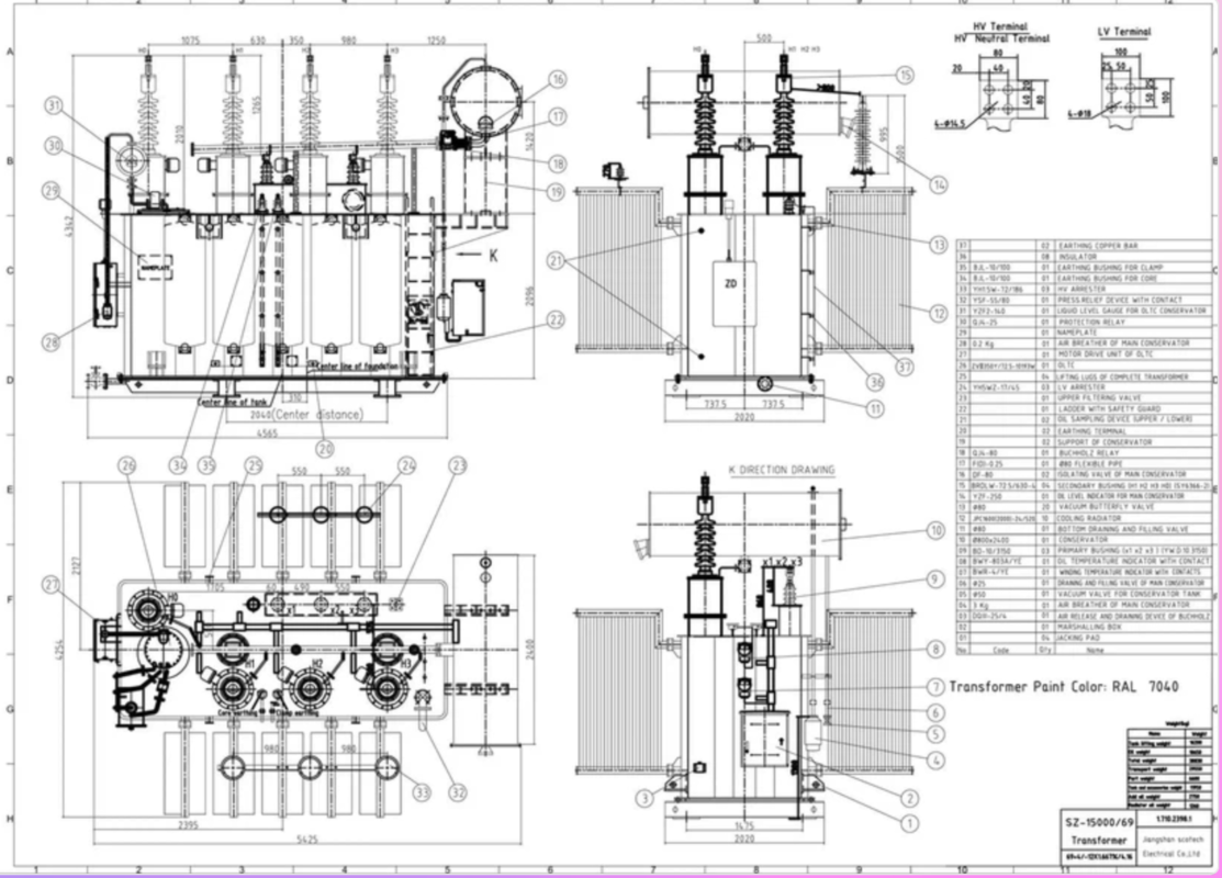
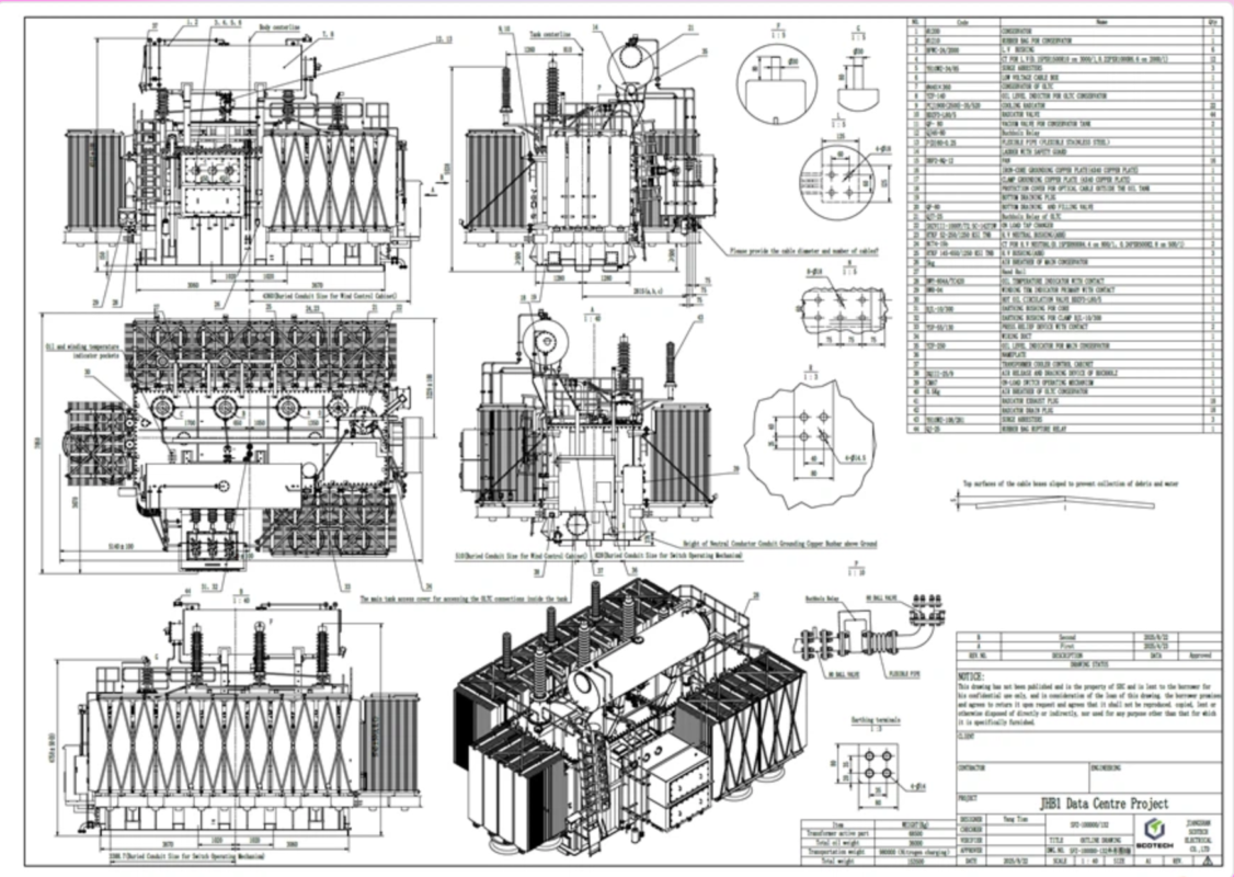
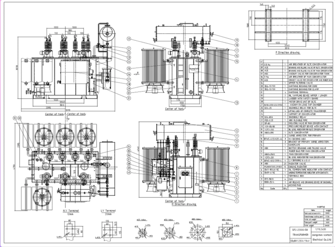
Review the Product Drawing Before Production
Review the following points before approving production:
| Drawing item | Buyer-side check |
| Overall dimensions | Confirm compatibility with the transformer room, doors, transport route, and available floor space |
| Total weight | Check foundation, crane, lifting, and transport capacity |
| HV terminal position | Confirm the incoming cable or busbar route |
| Rectifier-side terminals | Check the number, location, phase sequence, and current-carrying connection method |
| Terminal-to-rectifier distance | Coordinate busbar length, support, flexibility, and clearance |
| Lifting points | Confirm suitable lifting equipment and overhead space |
| Base arrangement | Check foundation channels, anchor bolts, wheels, or skid requirements |
| Cooling clearance | Reserve sufficient ventilation space |
| Maintenance access | Ensure that personnel can reach inspection and service points |
| Accessory location | Confirm visibility and access for monitoring and protection devices |
The product-page drawing should serve as a reference unless DHDL confirms it as the final design for the order.
Accordingly, request an order-specific general arrangement drawing after the engineering team confirms the transformer and rectifier data.
Testing and Quality Documentation
DHDL states that its transformer manufacturing process includes material preparation, core processing, winding production, insulation treatment, assembly, final inspection, and testing.
In addition, the company lists testing capabilities such as:
- Turns-ratio testing
- Winding DC-resistance testing
- Insulation-resistance testing
- Power-frequency withstand testing
- Induced-withstand-voltage testing
- No-load-loss testing
- Sealing-performance testing where applicable
However, test scope varies by transformer type and project standard. Therefore, request a product-specific inspection and test plan before placing the order.
For a phase-shifting rectifier transformer, the project may also need to confirm items such as:
- Ratio of every secondary winding
- Phase displacement
- Vector relationship
- Secondary-voltage balance
- Winding resistance
- Impedance
- No-load loss and current
- Load loss
- Insulation performance
- Temperature-rise verification, if required
- Accessory function
- Terminal identification
- Nameplate information
The final list must follow the approved standard, technical agreement, and transformer design.
Why Manufacturing and Testing Control Matter
In a phase-shifting rectifier transformer, the buyer depends on the accuracy and consistency of multiple electrical relationships.
For example, secondary-voltage deviation or phase-angle error may affect rectifier operation. Likewise, inconsistent impedance or connection errors can create unequal current sharing between rectifier sections.
Therefore, manufacturing control matters from the beginning of production, not only during final testing.
DHDL describes a manufacturing system covering:
- Incoming material inspection
- Core processing
- Winding production
- Insulation treatment
- Transformer assembly
- Finished-product inspection
- Routine testing
- Technical-document preparation
- Export packing
You can review these capabilities on the DHDL manufacturing capability page.
Before ordering, ask which production checks and final tests will apply to the proposed phase-shifting rectifier transformer.
Information to Include in Your RFQ
A short request such as “Please quote one rectifier transformer” does not provide enough information for an accurate proposal.
Instead, include the following data:
Electrical System Data
- Destination country
- Applicable standard
- Incoming voltage
- Frequency
- System fault level
- Earthing method
- Permitted voltage variation
- Existing harmonic information
DC Process Data
- Required DC voltage
- Required DC current
- Rated DC power
- Process type
- Continuous or intermittent operation
- Peak load
- Overload cycle
- Required control range
Rectifier Data
- Rectifier topology
- Pulse number
- Number of bridges
- Required AC input for each bridge
- Phase-shift requirement
- Rectifier manufacturer
- Rectifier data sheet
- Connection diagram
Transformer Data
- Required capacity
- Primary and secondary voltages
- Number of secondary windings
- Vector group
- Impedance requirement
- Tap requirement
- Cooling method
- Winding-material requirement
- Insulation level
- Monitoring accessories
- Enclosure requirement
Installation Data
- Indoor or outdoor installation
- Ambient temperature
- Relative humidity
- Altitude
- Dust or corrosion conditions
- Ventilation
- Maximum dimensions
- Maximum transport weight
- Cable or busbar connection
- Installation drawing
- Maintenance-clearance restrictions
Commercial and Document Requirements
- Quantity
- Project schedule
- Delivery destination
- Required test reports
- Required drawings
- Inspection requirements
- Third-party witness requirements
- Packing requirements
- Spare parts
- Documentation language
If some transformer parameters remain undecided, send DHDL the rectifier data sheet, single-line diagram, DC process requirements, and site conditions. The engineering team can then identify the remaining technical decisions.
Frequently Asked Questions
What is the main purpose of a phase-shifting rectifier transformer?
It supplies the voltage required by an industrial rectifier system and may provide several secondary outputs with defined phase relationships. Therefore, it can support a multi-pulse rectifier arrangement when the complete system is designed accordingly.
Can it reduce harmonics?
A properly engineered phase-shifting and multi-pulse rectifier system can reduce selected characteristic harmonics. However, actual performance depends on the pulse configuration, rectifier topology, transformer design, network impedance, existing harmonics, and operating load.
Consequently, buyers should request system calculations rather than rely on a general “low harmonic” claim.
Is a rectifier transformer the same as a distribution transformer?
No. A rectifier transformer supplies a nonlinear power-electronic load and must coordinate with the rectifier topology and DC process. By contrast, a distribution transformer usually supplies conventional AC loads.
How do I determine the correct capacity?
Start with the required DC output and rectifier efficiency. Then consider transformer losses, load cycle, harmonic duty, voltage regulation, overload requirements, ambient conditions, and future expansion.
The transformer and rectifier suppliers should confirm the final capacity together.
Which pulse configuration should I select?
The appropriate configuration depends on the project’s harmonic target, rectifier design, capacity, network conditions, available space, technical complexity, and budget.
Therefore, the buyer should not choose the pulse number independently from the rectifier-system design.
Why is short-circuit impedance important?
Impedance can influence fault current, voltage regulation, rectifier commutation, current sharing, and system performance. Accordingly, the transformer manufacturer and rectifier supplier should agree on the required value and tolerance.
Can DHDL customize the transformer?
DHDL states that it supports customized production according to voltage level, frequency, standard, installation environment, application, and project requirements.
Nevertheless, buyers should confirm the exact customization scope for the proposed phase-shifting rectifier transformer in the technical quotation.
What should I approve before production starts?
Approve at least:
- Technical data sheet
- Transformer–rectifier interface data
- Winding and phase-shifting arrangement
- General arrangement drawing
- Terminal diagram
- Dimensions and weight
- Accessory list
- Nameplate drawing
- Inspection and test plan
- Technical deviation list
- Document-delivery schedule
Select the Transformer Around the Complete DC Process
A phase-shifting rectifier transformer should not be purchased as an isolated catalogue product.
Instead, select it around the complete industrial DC power system:
- Start with the process DC voltage and current.
- Confirm the rectifier topology and pulse configuration.
- Define the required transformer secondary outputs.
- Coordinate phase displacement and impedance.
- Review harmonics and power-quality targets.
- Provide the actual load cycle and site conditions.
- Approve the transformer–rectifier interface.
- Review the product drawing.
- Confirm the test plan and acceptance criteria.
- Resolve every deviation before production.
By following this sequence, users can reduce interface errors, performance disputes, redesign work, and commissioning delays.
For a project-specific proposal, send DHDL your DC output requirements, rectifier data sheet, incoming voltage, pulse configuration, load profile, harmonic target, installation conditions, applicable standard, quantity, and destination country.
Contact DHDL to discuss a phase-shifting rectifier transformer for your industrial DC power system.