
Transformer Sizing for EV Fast Charging Stations: kVA Calculation, Grid Requirements & RFQ Checklist

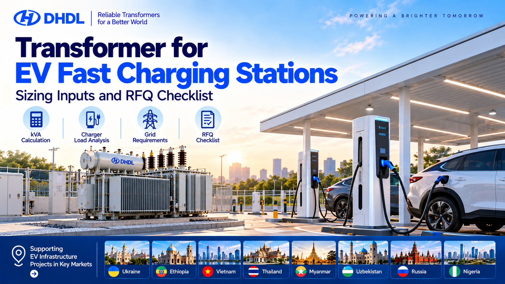
Installing DC fast chargers is only one part of building a reliable EV charging station. Behind every 120kW, 240kW, or 480kW charger is an electrical distribution system that must supply sufficient power, maintain acceptable voltage, and withstand repeated high-load operation.
For charging infrastructure projects in Thailand, Vietnam, Ethiopia, Nigeria, Uzbekistan, Myanmar, Ukraine, and Russia, transformer selection should begin with the actual charging demand and local utility connection requirements.
An undersized transformer can restrict simultaneous charging, cause excessive temperature rise, and limit expansion. An oversized transformer may increase equipment costs, no-load losses, and the size of associated switchgear.
This guide explains how to calculate transformer capacity for EV fast charging stations, select appropriate technical specifications, evaluate grid requirements, and prepare a complete transformer RFQ.
1. What Size Transformer Does an EV Fast Charging Station Need?
The required transformer capacity depends on more than the total rated power of the chargers.
Buyers should consider:
- Number of DC fast chargers
- Maximum AC input demand per charger
- Charger conversion efficiency
- Simultaneous charging demand
- Site energy-management limits
- Existing electrical loads
- Power factor and harmonic currents
- Future charger expansion
- Transformer cooling and installation conditions
For example, a station with four 240kW chargers has a total nominal DC output rating of 960kW.
However, the transformer supplies AC input power, not DC output power.
If the chargers operate at 95% conversion efficiency, their combined AC input demand at full output is approximately:
\[ P_{\mathrm{AC}}=\frac{960}{0.95}\approx1{,}011\text{ kW} \]
At a power factor of 0.98:
\[ S=\frac{1{,}011}{0.98}\approx1{,}032\text{ kVA} \]
If the engineering design adopts a 15% allowance:
\[ 1{,}032\times1.15\approx1{,}187\text{ kVA} \]
A 1,250kVA transformer may be considered for this illustrative configuration, subject to site loads, harmonic heating, temperature rise, and the final utility-approved design.
The 95% efficiency, 0.98 power factor, and 15% allowance are example assumptions—not universal charger specifications.
2. EV Charging Transformer Sizing Formula
For a preliminary estimate, the transformer apparent-power requirement can be expressed as:
\[ \boxed{S_{\mathrm{kVA}}= \frac{N\times P_{\mathrm{DC}}\times D} {\eta\times PF}\times(1+M)} \]
Where:
- N = Number of chargers
- PDC = Rated DC output power per charger in kW
- D = Assumed simultaneous demand factor
- η = Charger conversion efficiency
- PF = Input power factor
- M = Design allowance
This simplified formula assumes similar chargers and a reasonably uniform demand profile. For mixed charger ratings, calculate each charger group separately and combine the expected coincident demand.
The allowance must not be used as a substitute for checking actual thermal loading, harmonics, voltage regulation, and future expansion.
EV Fast Charging Transformer Sizing Examples
The following examples assume 95% charger efficiency, 0.98 input power factor, and a 15% design allowance.
| Charging Station | Demand Factor | Calculated kVA With Allowance | Candidate Transformer |
|---|---|---|---|
| 2 × 120kW | 100% | 296kVA | 315kVA |
| 4 × 120kW | 100% | 593kVA | 630kVA |
| 4 × 240kW | 100% | 1,186kVA | 1,250kVA |
| 6 × 240kW | 80% | 1,423kVA | 1,600kVA |
| 8 × 240kW | 80% | 1,897kVA | 2,000kVA |
| 4 × 480kW | 100% | 2,372kVA | 2,500kVA |
These values are illustrative preliminary selections, not final engineering approvals.
For example, an 80% demand factor is appropriate only when supported by an actual load study or an enforceable charging power-management system.
For commercial EV charging projects in Vietnam, Thailand, and Nigeria, this calculation can help estimate the initial transformer requirement before requesting a utility connection study.
3. Five Technical Specifications Buyers Must Confirm
3.1 Primary and Secondary Voltage
The transformer must match the available utility voltage and the charging equipment’s AC input requirements.
Illustrative configurations include:
| Parameter | Example Specification |
|---|---|
| Primary Voltage | 10kV / 11kV / 22kV / 33kV |
| Secondary Voltage | 400V / 415V |
| Frequency | 50Hz |
| Phase | Three-Phase |
| Vector Group | Dyn11, subject to system design |
| Tap Range | ±2 × 2.5%, if specified |
| Cooling | ONAN / AN / AF |
| Winding Material | Copper / Aluminum |
| Short-Circuit Impedance | Project Specific |
| Applicable Standards | IEC / Utility / Project Requirements |
These are example RFQ parameters. They do not mean every voltage combination is available for every DHDL model.
For projects in Thailand, Vietnam, Ethiopia, and Uzbekistan, confirm the actual utility supply voltage before selecting the transformer.
3.2 Transformer Impedance and Short-Circuit Current
Transformer impedance affects voltage regulation and prospective fault current.
For example, a 2,500kVA transformer supplying a 400V three-phase system has a rated secondary current of approximately:
\[ I=\frac{2{,}500{,}000}{\sqrt{3}\times400}\approx3{,}608\text{ A} \]
The low-voltage switchgear, circuit breakers, busbars, and cables must be coordinated with the calculated load and short-circuit conditions.
A transformer with lower impedance may produce higher prospective fault current. Therefore, impedance should not be selected independently from the electrical protection design.
3.3 Harmonics from DC Fast Chargers
DC fast chargers contain power-electronic conversion equipment.
Depending on the charger design, operating conditions, and filtering arrangement, they can introduce harmonic currents into the electrical system.
Before purchasing, request:
- Charger input power factor
- Total harmonic current distortion (THDi)
- Harmonic spectrum, where required
- Maximum AC input current
- Voltage operating range
- Power-quality compliance information
Hidden procurement risk: A transformer sized only from charger output kW may be thermally unsuitable if harmonic currents and actual input demand are ignored.
3.4 Cooling and Ambient Temperature
Outdoor charging stations may operate under high temperatures, dust, humidity, or cold-weather conditions.
For Thailand, Vietnam, Ethiopia, and Nigeria, buyers should provide the maximum site ambient temperature and installation details.
For Ukraine, Russia, and Uzbekistan, minimum temperatures, insulating-oil suitability, condensation, and cold-weather accessories may also require evaluation.
DHDL offers oil-immersed distribution transformers for outdoor power distribution applications, with cooling and environmental configurations reviewed according to project requirements.
3.5 Load Management and Future Expansion
Not every charger must operate at its maximum output simultaneously.
A station with intelligent load management may limit total charger input power to stay within the available electrical capacity.
However, the transformer should not be downsized based on an assumed demand factor unless that limit is technically enforced and acceptable for station operations.
Buyers should also consider future expansion.
A charging station starting with four chargers may require eight or twelve chargers later.
The transformer, switchgear, cable routes, and substation footprint should be evaluated against the expansion plan.
4. Real Project Case: DHDL Heavy-Duty Truck Fast Charging Station
DHDL’s Jining Zoucheng Heavy-Duty Truck Charging Station Project provides a practical example of transformer selection for large-scale DC fast charging infrastructure.
The project serves electric heavy-duty trucks used in industrial logistics and coal transportation. It integrates high-power DC charging, transformer substations, photovoltaic generation, and battery energy storage.
Published Project Specifications
| Project Parameter | DHDL Project Data |
|---|---|
| Location | Jining, Shandong, China |
| Application | Heavy-Duty Truck Fast Charging |
| Main Transformers | 2 × 20,000kVA |
| Main Transformer Voltage | 35/10.5kV |
| Main Transformer Model | SZ20-20000/35/10.5 |
| Cooling Method | ONAN |
| Vector Group | YNd11 |
| Box-Type Substations | 16 × 2,500kVA |
| DC Fast Chargers | 64 × 480kW |
| Charger Output Voltage | 200–1,000V |
| Solar PV System | 4MWp |
| Battery Energy Storage | 10MW / 20MWh |
| Equipment Delivery | Within 60 Days |
The combined rated DC output of the charging equipment is:
\[ 64\times480=30{,}720\text{ kW} \]
That is 30.72MW of nominal charger output capacity.
This figure is not the same as the site’s measured simultaneous grid demand. Actual demand depends on charger utilization, AC conversion losses, load management, and the operation of the PV and energy storage systems.
The project uses two 20MVA main transformers and sixteen 2,500kVA box-type substations to distribute power across the charging infrastructure.
DHDL reports that the main transformer production cycle was 45 days, the box-type substation production cycle was 35 days, and all equipment was delivered within 60 days.
What Can EV Charging Buyers Learn from This Project?
First, large charging stations should be designed as complete electrical systems rather than collections of individual chargers.
Second, a high-power charging project may require several distribution transformers or prefabricated substations instead of one large low-voltage transformer.
Third, PV and battery energy storage can support energy management, but their contribution to reducing grid demand must be evaluated using an actual operating strategy.
For proposed electric truck charging stations in Thailand, Vietnam, Nigeria, and Uzbekistan, this project provides a useful reference for integrated transformer, switchgear, charging, and energy-storage planning.
It should not be interpreted as a standard configuration suitable for every charging station.
5. Transformer Selection for Different EV Charging Applications
The electrical requirements of a highway charging hub can differ substantially from those of a bus depot or commercial parking facility.
| Application | Typical Engineering Priority | Transformer Considerations |
|---|---|---|
| Highway DC Fast Charging | High peak demand | Simultaneity, cooling, expansion |
| Electric Bus Depot | Scheduled fleet charging | Charging timetable, demand control |
| Heavy-Duty Truck Charging | High-power charging | MV connection, multiple substations |
| Shopping Mall Charging | Shared building demand | Existing loads, spare capacity |
| Industrial Fleet Charging | Predictable operating schedules | Load profile, voltage regulation |
| PV + EV Charging Station | Renewable energy integration | Bidirectional power, EMS, protection |
For example, a bus depot in Vietnam may use scheduled overnight charging to control peak demand.
A commercial fast-charging hub in Thailand may need to account for high ambient temperature and simultaneous charger operation.
A logistics charging station in Nigeria or Ethiopia should evaluate its actual utility connection, site conditions, and backup-power requirements.
In Myanmar, charging-station developers may need to place particular emphasis on site-specific supply reliability and power-management arrangements.
The correct transformer rating depends on these operating conditions, not simply the number of charging connectors.
6. Hidden Costs Buyers Often Miss
A low transformer quotation does not necessarily mean a lower total charging-station cost.
Transformer and Charger Ratings May Not Match
A charger advertised as 240kW usually refers to its DC output rating.
The transformer must supply the corresponding AC input, which can be higher because of conversion losses.
Always request the manufacturer’s maximum AC input power and current.
Low-Voltage Switchgear May Become the Bottleneck
A 2,500kVA transformer supplying 400V has a rated secondary current of approximately 3,608A.
The low-voltage distribution cabinet, busbar system, circuit breakers, and cables must be designed for the applicable current and fault conditions.
A transformer upgrade may therefore require switchgear upgrades.
Utility Connection Costs Can Exceed Expectations
A proposed EV charging station may require:
- Medium-voltage grid connection
- New transformer substation
- MV switchgear
- LV distribution cabinets
- Metering equipment
- Protection relays
- Cable installation
- Civil works
- Utility approval and commissioning
These costs should be evaluated before finalizing the transformer procurement budget.
Transformer Losses Affect Long-Term Operating Costs
Fast-charging station utilization may vary significantly throughout the day.
A transformer remains energized during low-demand periods, so no-load losses matter alongside load losses.
Buyers should compare guaranteed loss values and expected annual loading rather than choosing a transformer based only on initial purchase price.
Delivery Time May Affect the Opening Date
Transformer manufacturing is only one stage of the project.
Drawing approval, factory testing, shipping, customs clearance, installation, and utility energization can all affect the final opening schedule.
For overseas projects in Ethiopia, Thailand, Vietnam, Uzbekistan, and Nigeria, include the required site delivery date in the RFQ rather than requesting only the shortest factory production time.
7. EV Fast Charging Transformer RFQ Checklist
Before requesting a transformer quotation, provide the following information.
| RFQ Item | Buyer Input |
|---|---|
| Destination Country | __________ |
| Charging Station Type | Highway / Bus / Truck / Commercial |
| Charger Quantity | _____ Units |
| Charger Rated DC Output | _____ kW |
| Maximum AC Input per Charger | _____ kW / kVA |
| Charger Efficiency | _____ % |
| Input Power Factor | _____ |
| Simultaneous Demand Factor | _____ % |
| Maximum Station Demand | _____ kW |
| Existing Site Load | _____ kW |
| Future Expansion | _____ Chargers |
| Required Transformer Capacity | _____ kVA |
| Primary Voltage | _____ kV |
| Secondary Voltage | _____ V |
| Frequency | 50 / 60Hz |
| Vector Group | __________ |
| Short-Circuit Impedance | _____ % |
| Transformer Type | Oil-Immersed / Dry-Type |
| Cooling Method | ONAN / AN / AF |
| Winding Material | Copper / Aluminum |
| Harmonic Requirements | THDi / Harmonic Spectrum |
| Maximum Ambient Temperature | _____ °C |
| Minimum Ambient Temperature | _____ °C |
| Altitude | _____ m |
| Applicable Standard | IEC / Utility / Project |
| PV System | _____ kWp |
| Energy Storage | _____ kW / kWh |
| Quantity | _____ Units |
| Required Delivery Date | __________ |
Recommended RFQ Attachments
- Single-Line Diagram (SLD)
- Charger technical datasheets
- Maximum AC input power specifications
- Charging demand profile
- Utility connection requirements
- Transformer sizing calculation
- Short-circuit study
- Protection coordination study
- Power-quality and harmonic requirements
- Existing electrical equipment information
- PV and BESS system specifications, if applicable
- Site layout and environmental data
- Project construction schedule
Providing these documents helps the manufacturer identify missing technical information before issuing a final quotation.
How to Calculate Transformer Capacity (kVA): Formula, Sizing Examples & Buyer’s Checklist
8. EV Charging Transformer Solutions from DHDL
DHDL supplies oil-immersed distribution transformers, dry-type transformers, power transformers, prefabricated substations, and electrical distribution equipment for industrial and infrastructure applications.
Its published 6–38.5kV oil-immersed distribution transformer series covers rated capacities of 30–2,500kVA, with voltage, tap range, vector group, accessories, and other configurations subject to the selected product and project requirements.
For larger charging infrastructure, DHDL’s Jining Zoucheng project demonstrates experience supplying main power transformers, box-type substations, DC chargers, and energy storage equipment within one integrated project.
For EV charging developments in Thailand, Vietnam, Ethiopia, Nigeria, Myanmar, Uzbekistan, Ukraine, and Russia, buyers can submit their project requirements for technical evaluation, subject to applicable local standards and trade requirements.
To request a technical proposal, provide:
Charger Quantity + Maximum AC Input + Simultaneous Demand + HV/LV Voltage + Site Conditions + Expansion Plan + Destination
The goal is not simply to buy a transformer large enough for today’s chargers.
It is to design a reliable, expandable power distribution system that supports actual charging demand without unnecessary infrastructure costs.
DHDL — Transformer and Integrated Power Distribution Solutions for EV Charging Infrastructure.
Website: https://dinghongtransformer.com/
Contact: Request a Transformer Quotation