
Power Factor Correction Panel Sizing: kVAR Calculation, Detuned Reactors & RFQ Checklist


A power factor correction panel can help industrial facilities reduce unnecessary reactive power demand, improve power factor, and make better use of existing electrical distribution capacity.
However, choosing a capacitor bank based only on transformer kVA or a supplier’s standard cabinet size can lead to overcompensation, harmonic resonance, overheating, and unnecessary equipment costs.
For factories, industrial parks, commercial buildings, and infrastructure projects in Vietnam, Thailand, Ethiopia, Nigeria, Uzbekistan, Ukraine, Myanmar, and Russia, power factor correction panel sizing should begin with actual load measurements and the electrical system’s operating conditions.
This guide explains how to calculate the required compensation capacity in kVAR, compare automatic and fixed capacitor banks, evaluate harmonic risks, and prepare an accurate RFQ for a low-voltage power factor correction panel.
1. What Is a Power Factor Correction Panel?
A power factor correction panel, also called an APFC panel or automatic capacitor bank, supplies capacitive reactive power to compensate for inductive loads.
Industrial equipment such as induction motors, pumps, compressors, and certain transformers consumes reactive power in addition to real power.
When the power factor is low, the electrical system may carry more current than necessary to deliver the same real power.
A properly designed compensation panel can help:
- Improve the operating power factor
- Reduce reactive power drawn from the upstream network
- Reduce current in upstream cables and transformers
- Reduce some electrical distribution losses
- Improve utilization of existing distribution equipment
- Reduce reactive energy charges where the utility tariff provides an incentive
DHDL’s GGJ low-voltage reactive power compensation cabinet is a relevant product category for industrial and commercial low-voltage distribution applications.
The exact cabinet configuration depends on the required compensation capacity, system voltage, switching method, protection arrangement, and power-quality conditions.
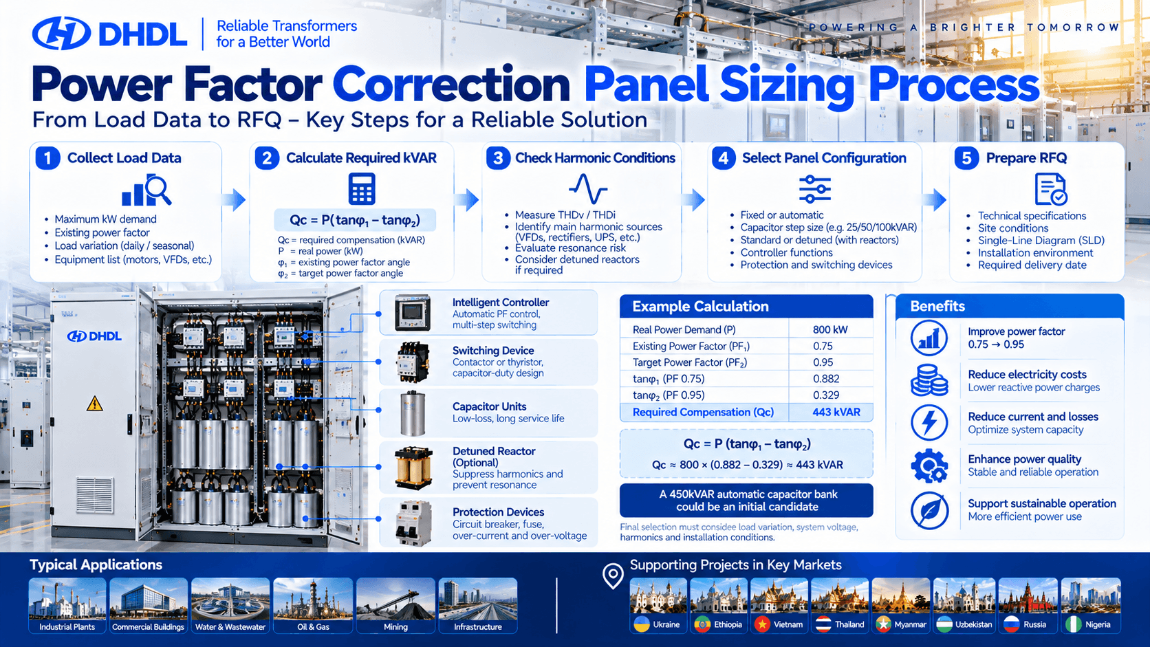
2. How to Calculate Power Factor Correction Panel Capacity
The required capacitor bank capacity is generally expressed in kVAR (kilovolt-amperes reactive).
For a simplified steady-state calculation with sinusoidal voltage and current:
\[ \boxed{Q_c=P(\tan\phi_1-\tan\phi_2)} \]
Where:
- Qc = Required compensation capacity in kVAR
- P = Real power demand in kW
- φ1 = Angle corresponding to the existing power factor
- φ2 = Angle corresponding to the target power factor
The angle is calculated using:
\[ \phi=\cos^{-1}(PF) \]
Example: Correcting a Factory from 0.75 to 0.95 Power Factor
Assume an industrial facility has:
| พารามิเตอร์ | Example Value |
|---|---|
| Real Power Demand | 800kW |
| Existing Power Factor | 0.75 |
| Target Power Factor | 0.95 |
| Existing Apparent Power | 1,067kVA |
| Target Apparent Power | 842kVA |
The required compensation is:
\[ Q_c=800(\tan(\cos^{-1}0.75)-\tan(\cos^{-1}0.95)) \]
\[ Q_c\approx800(0.882-0.329) \]
\[ \boxed{Q_c\approx443\text{ kVAR}} \]
A nominal 450kVAR automatic capacitor bank could be an initial candidate for this example.
However, the final selection must consider load variation, capacitor voltage rating, harmonic distortion, available standard steps, and the actual system operating voltage.
Hidden procurement risk: A calculated 443kVAR requirement does not automatically mean that a 450kVAR capacitor bank will deliver exactly 450kVAR at every installation voltage.
Capacitor reactive output varies approximately with the square of the applied voltage, and detuned reactor arrangements can change the relationship between component ratings and net compensation.
3. Power Factor Correction Sizing Examples
The following table illustrates typical compensation calculations.
| Real Power | Existing PF | Target PF | Calculated Compensation |
|---|---|---|---|
| 200kW | 0.75 | 0.95 | 111kVAR |
| 400kW | 0.80 | 0.95 | 169kVAR |
| 600kW | 0.85 | 0.95 | 175kVAR |
| 800kW | 0.75 | 0.95 | 443kVAR |
| 1,000kW | 0.80 | 0.95 | 421kVAR |
| 1,500kW | 0.85 | 0.98 | 625kVAR |
These values are calculated examples, not fixed cabinet recommendations.
The required installed capacity should be selected using the facility’s measured demand profile and power-quality assessment.
For industrial projects in Vietnam, Thailand, Nigeria, and Ethiopia, a seven-day or longer load and power-factor recording period may be useful where demand varies significantly between shifts.
4. Automatic vs Fixed Power Factor Correction Panels
Not every facility needs the same switching arrangement.
| พารามิเตอร์ | Fixed Capacitor Bank | Automatic PFC Panel |
|---|---|---|
| Compensation | Fixed output | Multiple switched steps |
| Best-Suited Load | Relatively stable | Variable industrial loads |
| Controller | May not be required | Automatic PF controller |
| Switching | Fixed or manually controlled | Contactors or suitable electronic switches |
| Main Risk | Overcompensation at light load | Poor step design or excessive switching |
| Procurement Focus | Correct fixed kVAR | Step size, response time and control logic |
For factories in Vietnam, Thailand, and Uzbekistan operating several production shifts, automatic power factor correction may be appropriate when reactive power demand changes throughout the day.
A facility with relatively constant inductive demand may use a fixed capacitor bank, provided the operating conditions justify it.
Why Capacitor Step Size Matters
Suppose a factory requires approximately 450kVAR of compensation at peak demand.
One possible automatic configuration is:
25 + 25 + 50 + 50 + 100 + 100 + 100 = 450kVAR
This is only an illustrative step arrangement.
Smaller steps allow finer adjustment at low loads, while larger steps provide greater compensation during high demand.
For rapidly changing loads, the supplier should also evaluate switching speed and equipment duty.
5. When Do You Need Detuned Reactors?
Harmonics are one of the most important hidden risks in power factor correction projects.
Factories using variable-frequency drives, rectifiers, UPS systems, welding equipment, and other nonlinear loads may experience significant harmonic distortion.
Connecting a conventional capacitor bank to such a network can create resonance conditions and increase current through the capacitors.
Depending on the power-quality study, the solution may require a detuned capacitor bank using series reactors.
Before selecting the panel, request:
- Voltage and current harmonic measurements
- Total harmonic voltage distortion (THDv)
- Total harmonic current distortion (THDi)
- Individual harmonic components
- Transformer capacity and impedance
- Existing capacitor banks
- Variable-frequency drive and rectifier loads
- Utility power-quality requirements
Standard vs Detuned Compensation
| รายการ | Standard Capacitor Bank | Detuned Capacitor Bank |
|---|---|---|
| Main Components | Capacitors and switching devices | Capacitors with series reactors |
| Harmonic Environment | Suitable after system assessment | Used where resonance risk requires mitigation |
| Design Complexity | Lower | Higher |
| Cabinet Space | Generally smaller | Additional reactor space |
| Heat Dissipation | Capacitor and switching losses | Additional reactor losses and heat |
| Main Buyer Check | kVAR and switching | Harmonic study, tuning and thermal design |
A detuned reactor arrangement is not automatically a complete harmonic filter.
Hidden buyer tip: Do not specify a 7% reactor solely because it appears in another supplier’s quotation. Reactor tuning, capacitor voltage rating, harmonic conditions and component thermal limits must be engineered together.
6. Practical Application Scenario: Industrial Factory in Thailand
Consider an illustrative manufacturing facility in Thailand operating motors, compressors and variable-frequency drives.
The facility has an 800kW measured maximum demand and an existing power factor of 0.75.
The project aims to improve the power factor to approximately 0.95.
The preliminary compensation requirement is 443kVAR.
A possible procurement process would be:
- Measure the load and power factor over representative operating shifts.
- Confirm the required compensation capacity.
- Review harmonic distortion and resonance risk.
- Decide whether a standard or detuned APFC panel is appropriate.
- Select capacitor step sizes and switching equipment.
- Confirm cabinet ventilation, protection and installation space.
- Approve drawings and testing requirements before manufacturing.
For a project in Vietnam, the same process may require additional attention to humidity, ventilation and coastal corrosion where applicable.
For Ethiopia, site altitude and ambient temperature should be provided for component thermal review.
For Nigeria, the buyer should confirm actual voltage variation, load profile and site power-quality conditions.
For Uzbekistan, seasonal temperature variation, dust and the electrical-room environment may influence the cabinet design.
These are engineering application examples, not claims that DHDL has supplied a specific 450kVAR panel to these facilities.
DHDL Product Reference
DHDL’s published GGJ Low-Voltage Reactive Power Compensation Cabinet integrates compensation capacitors, intelligent controllers, switching devices, protection components, busbars and monitoring functions.
The manufacturer identifies industrial facilities, commercial buildings, substations and transformer low-voltage distribution systems as intended applications. Compensation capacity, voltage level, capacitor configuration, controller type and protection design are project-specific.
A fixed kVAR range, standard cabinet dimensions or guaranteed project power-factor improvement should not be assumed without an approved technical proposal.
7. Hidden Costs Buyers Should Check Before Ordering
Two quotations for a 450kVAR power factor correction panel may differ significantly in price because their technical scope is different.
Common hidden costs include:
- Detuned reactors and higher-rated capacitors
- Additional ventilation or forced cooling
- Capacitor-duty contactors or thyristor switching
- Short-circuit protection and busbar upgrades
- Current transformers (CTs) and controller wiring
- Harmonic measurements and commissioning
- Replacement capacitors and maintenance access
Another common mistake is installing the compensation panel at the wrong measurement or connection point.
For example, a current transformer installed incorrectly may cause the automatic controller to switch capacitor steps improperly.
Procurement tip: Request a Single-Line Diagram showing the capacitor bank connection, CT location, incoming protection and controller wiring before approving production.
8. Power Factor Correction Panel RFQ Checklist
Use the following checklist when requesting a quotation from a manufacturer.
| RFQ Parameter | Buyer Input |
|---|---|
| Destination Country | __________ |
| Application | Factory / Commercial / Substation |
| System Voltage | _____ V |
| ความถี่ | 50 / 60Hz |
| Phase | Three-Phase |
| Transformer Capacity | _____ kVA |
| Transformer Impedance | _____ % |
| Maximum Real Power | _____ kW |
| Existing Power Factor | _____ |
| Target Power Factor | _____ |
| Required Compensation | _____ kVAR |
| Load Variation | Stable / Variable / Rapid |
| Compensation Type | Fixed / Automatic |
| Capacitor Steps | _____ Steps |
| Switching Method | Contactor / Thyristor |
| Harmonic Measurements | THDv / THDi / Spectrum |
| Detuned Reactors | Required / To Be Evaluated |
| Controller Functions | __________ |
| Short-Circuit Rating | _____ kA |
| Incoming Protection | __________ |
| Cabinet IP Rating | __________ |
| Installation | Indoor / Outdoor |
| Maximum Temperature | _____ °C |
| Altitude | _____ m |
| Communication | Modbus / Other |
| Applicable Standards | IEC / Local / Project |
| Quantity | _____ Units |
| Delivery Destination | __________ |
| Required Delivery Date | __________ |
Recommended RFQ Attachments
- Single-Line Diagram (SLD)
- Electricity bills showing reactive energy charges, if applicable
- Load and power-factor measurement records
- Transformer nameplate
- Harmonic measurement report
- Existing capacitor bank specifications
- Electrical-room layout
- Installation environment details
- Applicable technical standards
- Required factory testing and documentation
For buyers in Ukraine, Ethiopia, Vietnam, Thailand, Myanmar, Uzbekistan, Russia and Nigeria, provide the exact project location and site conditions rather than assuming one standard cabinet configuration will fit every market.
9. Power Factor Correction Solutions from DHDL
DHDL manufactures power distribution equipment for industrial, commercial, utility and infrastructure applications.
Its GGJ low-voltage reactive power compensation cabinet can be configured with capacitors, automatic controllers, switching devices, protection equipment and monitoring functions according to project requirements.
DHDL also supplies low-voltage distribution cabinets, transformers and related equipment, allowing buyers to discuss electrical interfaces as part of a wider distribution project.
For industrial power factor correction projects in Vietnam, Thailand, Ethiopia, Nigeria, Uzbekistan, Ukraine, Myanmar and Russia, submit the following information for technical review:
System Voltage + Maximum kW + Existing PF + Target PF + Harmonic Data + Transformer Specifications + Site Conditions + Quantity
A properly specified power factor correction panel should deliver the required compensation while avoiding unnecessary switching, resonance risks and installation changes.
DHDL — Customized Power Distribution and Reactive Power Compensation Solutions for Global Industrial Projects.
Website: https://dinghongtransformer.com/
Product: GGJ Low-Voltage Reactive Power Compensation Cabinet