
Parallel Operation of Transformers: Compatibility Requirements, Common Risks & Procurement Checklist

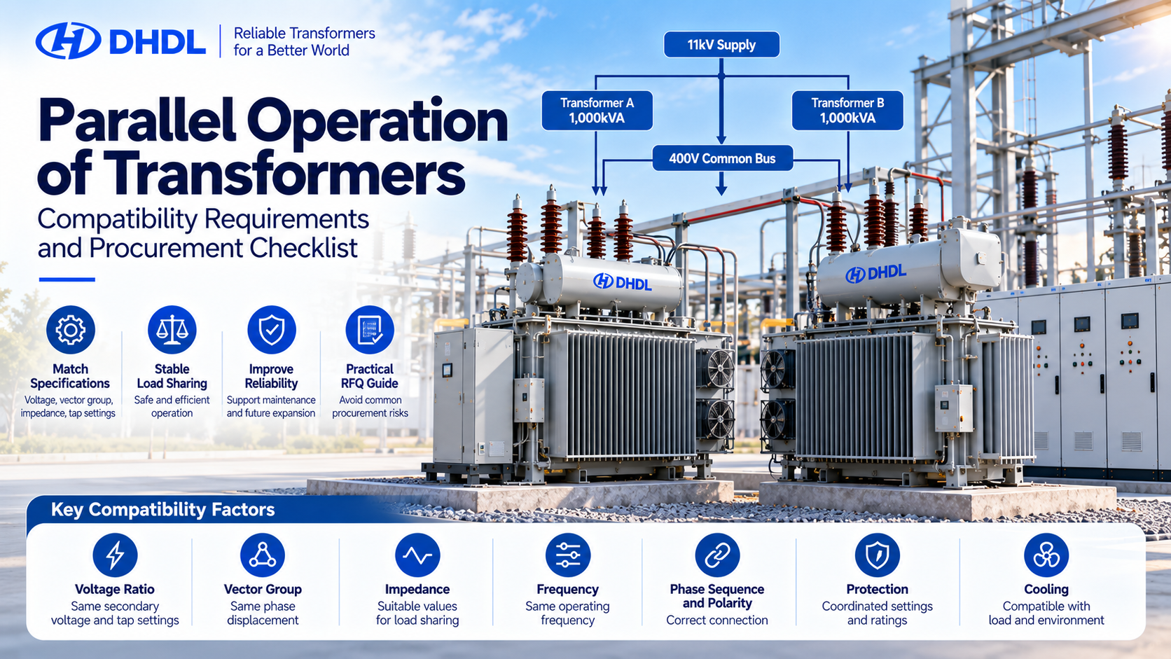
Can two transformers with the same capacity operate in parallel?
Not necessarily.
Parallel operation of transformers allows two or more transformers to supply a common electrical bus simultaneously. This arrangement is commonly used in industrial plants, substations, data centers, commercial facilities, and power distribution networks.
It can increase available capacity, improve operational flexibility, and support maintenance without shutting down the entire electrical system.
However, connecting two transformers with matching kVA ratings does not guarantee safe operation.
Differences in voltage ratio, vector group, short-circuit impedance, tap settings, and phase sequence can cause circulating currents, uneven load sharing, overheating, and protection problems.
DHDL’s existing technical guidance identifies these electrical characteristics as essential checks before parallel operation.
For EPC contractors and international transformer buyers, the main question is:
How can you confirm that a new transformer is compatible with an existing transformer before placing an order?
This guide explains the key technical requirements, practical load-sharing calculations, common procurement mistakes, and the information buyers should include in a transformer RFQ.
1. What Is Parallel Operation of Transformers?
Parallel transformer operation means connecting two or more transformers to a common bus so they can supply the same electrical load.
A typical industrial system may use the following arrangement:
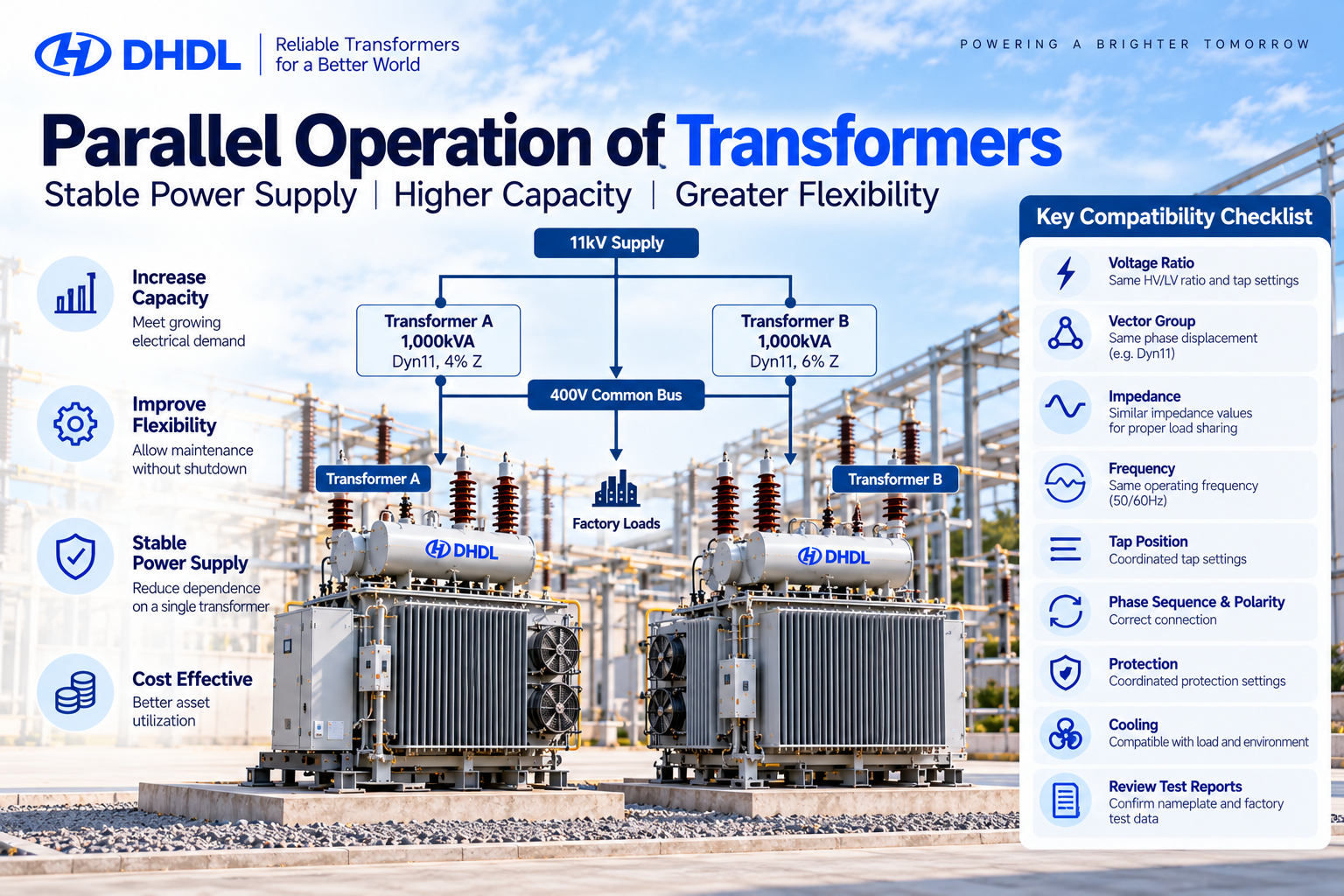
11kV Supply → Transformer A (1,000kVA) → 400V Common Bus
11kV Supply → Transformer B (1,000kVA) → 400V Common Bus
Both transformers contribute power to the connected loads when the system is designed and operated correctly.
The main reasons for using parallel transformers include:
– Increasing available power capacity
– Supporting future load expansion
– Improving operational flexibility
– Allowing planned maintenance
– Reducing dependence on a single transformer
– Supporting redundancy requirements
However, two 1,000kVA transformers do not automatically provide 2,000kVA of usable capacity under every operating condition.
Their load-sharing characteristics, cooling limits, protection arrangements, and operating conditions must be evaluated first.
Related Articles:
Can Transformers Operate in Parallel? Key Requirements for Load Sharing
Transformer Impedance Explained: Why It Matters for Fault Current and System Design
2. Transformer Parallel Operation Requirements
Before connecting transformers in parallel, engineers should compare their electrical characteristics.
| Parameter | Compatibility Requirement | Risk if Incorrect |
|---|---|---|
| Voltage Ratio | Compatible HV/LV ratios | Circulating current |
| Vector Group | Compatible phase displacement | Severe fault or circulating current |
| Phase Sequence | Must match | Incorrect phase connection |
| Polarity | Correct terminal polarity | Connection fault |
| Частота | Same operating frequency | Incompatible operation |
| Импеданс | Suitable values for load sharing | Unequal loading |
| Rated Capacity | Compatible with load-sharing design | Overloading |
| Tap Position | Coordinated secondary voltages | Circulating current |
| Protection | Coordinated settings and ratings | Incorrect fault clearing |
| Grounding | Compatible system arrangement | Protection and earth-fault issues |
These parameters should be confirmed through the existing transformer nameplate, factory test reports, electrical drawings, and engineering calculations.
Voltage Ratio and Tap Position
Transformers operating in parallel must produce compatible secondary voltages.
For example, two transformers may both be labeled 11/0.4kV, but different tap positions can produce different no-load secondary voltages.
This voltage difference may create circulating current even when the external load is small.
Buyers should confirm:
– Rated HV voltage
– Rated LV voltage
– Available tap positions
– Tap changer type
– Actual operating tap position
– Measured voltage ratio
For transformers equipped with on-load tap changers, the voltage-control strategy must also be coordinated.
Vector Group and Phase Sequence
The transformer vector group defines winding connections and phase displacement.
For example, Dyn11 and Dyn1 have different phase relationships and should not be treated as interchangeable for direct parallel connection.
Even if the rated capacity and voltage ratio match, incompatible phase displacement can create a dangerous connection condition.
Phase sequence, terminal identification, and polarity must also be verified before closing the common-bus connection.
Procurement tip: Never approve a replacement or additional transformer based only on kVA and voltage. Include the existing vector group in the purchase specification.
3. Why Transformer Impedance Matters for Load Sharing
Short-circuit impedance is one of the most important parameters for parallel transformer operation.
It affects how much load each transformer carries.
When two transformers have compatible secondary voltages but different impedances, the lower-impedance unit generally carries a greater share of the load.
This can cause one transformer to reach its rated capacity before the other.
Consider two transformers with equal rated capacity:
| Parameter | Transformer A | Transformer B |
|---|---|---|
| Rated Capacity | 1,000kVA | 1,000kVA |
| Voltage | 11/0.4kV | 11/0.4kV |
| Vector Group | Dyn11 | Dyn11 |
| Импеданс | 4% | 6% |
| Cooling | ONAN | ONAN |
Assuming compatible secondary voltages, similar impedance angles, and the same impedance base, their approximate load sharing is inversely proportional to impedance.
At a total load of 1,500kVA:
Transformer A Load = 1,500 × 6 / (4 + 6) = 900kVA
Transformer B Load = 1,500 × 4 / (4 + 6) = 600kVA
Illustrative load sharing at 1,500kVA
Transformer A · 4% impedance
900 kVA
90% of rated capacity
Transformer B · 6% impedance
600 kVA
60% of rated capacity
Illustrative calculation only. Actual load sharing depends on complex impedance, voltage matching, tap settings, and system conditions.
At a total load of 1,800kVA, the same simplified calculation gives approximately 1,080kVA for Transformer A and 720kVA for Transformer B.
Transformer A would exceed its 1,000kVA rating while Transformer B remains below its rating.
The hidden risk is that the combined nameplate capacity may be greater than the safely usable capacity of the parallel arrangement.
DHDL’s transformer impedance guidance similarly highlights unequal load sharing and overheating as risks when impedance characteristics are poorly matched.
4. Can Transformers with Different Capacities Operate in Parallel?
Yes, transformers with different kVA ratings can sometimes operate in parallel.
However, their voltage ratios, phase relationships, impedance characteristics, and protection arrangements must be compatible.
For example, consider:
| Parameter | Transformer A | Transformer B |
|---|---|---|
| Capacity | 1,000kVA | 2,000kVA |
| Voltage | 11/0.4kV | 11/0.4kV |
| Vector Group | Dyn11 | Dyn11 |
| Импеданс | 6% | 6% |
| Частота | 50Hz | 50Hz |
Under idealized conditions with matched per-unit impedance and impedance angle, load sharing is approximately proportional to rated capacity.
At a total load of 2,400kVA:
– Transformer A carries approximately 800kVA.
– Transformer B carries approximately 1,600kVA.
Both operate at approximately 80% of their rated capacity.
However, this is a simplified engineering example, not a complete approval for parallel operation.
Actual suitability requires a review of impedance tolerances, tap settings, voltage regulation, cooling, fault levels, and protection coordination.
5. Real Project Context: Industrial Park Transformer Expansion in Thailand
DHDL’s Thailand industrial park project provides a relevant example of transformer capacity expansion.
Related Case Studies:
Thailand Industrial Park Power Distribution Expansion Project
According to DHDL’s published project information, the company supplied an oil-immersed distribution transformer for an industrial park experiencing growing electrical demand.
| Project Parameter | Published Specification |
|---|---|
| Country | Таиланд |
| Application | Industrial Park Power Distribution |
| Transformer Model | S-8000/33 |
| Rated Capacity | 8,000kVA |
| Voltage | 33/0.416kV |
| Частота | 50Hz |
| Cooling | ONAN |
| Installation | Outdoor |
| Production and Testing | 38 Days |
The industrial park required additional power capacity to support expanding factory operations.
The published project describes a capacity expansion, not a confirmed parallel-transformer installation. It is therefore useful as a procurement scenario rather than evidence that this specific transformer operated in parallel.
If an EPC contractor planned to connect a new transformer to an existing common bus in a similar expansion project, additional engineering checks would be necessary.
These would include:
– Existing transformer capacity and voltage ratio
– Existing transformer vector group
– Measured short-circuit impedance
– Existing tap settings
– Common-bus configuration
– Transformer loading records
– Circuit-breaker ratings
– Protection coordination
– Short-circuit calculations
– Earthing arrangements
The key lesson is that adding transformer capacity and approving parallel operation are two different engineering decisions.
6. Hidden Procurement Risks Buyers Often Miss
Existing Transformer Data May Be Incomplete
A buyer may have the existing transformer nameplate but no factory test report.
The nameplate is useful, but it may not provide all the information required to assess actual compatibility, especially if the transformer has been repaired or modified.
For older equipment, engineers may need additional inspection or testing before finalizing a parallel-operation design.
Tap Settings May Change After Installation
Even when two transformers have compatible nameplate voltage ratios, their operating taps may differ.
This can create secondary voltage differences and circulating currents.
For projects using OLTC equipment, automatic voltage regulation and tap-control coordination should be included in the system design.
Adding a Transformer Can Increase Fault Current
Connecting additional transformers to a common bus can increase the prospective short-circuit current.
The existing low-voltage switchgear may no longer have adequate interrupting or withstand capability.
Before expansion, review:
– Main circuit breakers
– Busbar short-time withstand rating
– Protection relay settings
– Cable short-circuit ratings
– Earthing system
– Transformer differential protection where applicable
– Busbar protection where applicable
Redundancy Does Not Mean Unlimited Backup Capacity
A factory may install two 1,000kVA transformers and expect uninterrupted operation if one is unavailable.
However, if the normal facility load is 1,600kVA, the remaining transformer cannot automatically carry the entire load.
The design may require load shedding, additional capacity, or a different redundancy arrangement.
Hidden buyer tip: Specify both the normal parallel operating load and the maximum load that must remain supplied when one transformer is unavailable.
7. Factory Testing and Commissioning Requirements
Transformer compatibility should be checked before delivery and verified before parallel operation.
Typical factory documentation may include:
– Voltage ratio test report
– Winding resistance test report
– Vector group verification
– Short-circuit impedance test results
– No-load and load-loss test results
– Insulation test reports
– Tap changer documentation
– Nameplate drawing
– General Arrangement Drawing
Before commissioning, qualified electrical engineers should also review the site installation, terminal connections, phase sequence, polarity, protection settings, grounding, and expected circulating current.
The commissioning plan should include the appropriate checks required by the project’s standards and electrical design.
Parallel connection should never be attempted solely because the transformer nameplates appear similar.
8. Parallel Transformer Procurement Checklist
When requesting a new transformer for an existing parallel system, send the manufacturer both the proposed new-transformer requirements and the existing-transformer data.
| RFQ Item | Buyer Input |
|---|---|
| Application | Industrial / Utility / Data Center |
| New Transformer Capacity | _____ kVA / MVA |
| Existing Transformer Capacity | _____ kVA / MVA |
| HV Voltage | _____ kV |
| LV Voltage | _____ V / kV |
| Частота | 50 / 60Hz |
| Phase | Three Phase / Other |
| Vector Group | __________ |
| Existing Transformer Impedance | _____ % |
| Required New Transformer Impedance | _____ % |
| Tap Range | __________ |
| Tap Changer | OCTC / OLTC |
| Existing Tap Position | __________ |
| Метод охлаждения | __________ |
| Winding Material | Copper / Aluminum |
| Normal Combined Load | _____ kVA |
| Maximum Combined Load | _____ kVA |
| Required N-1 Load | _____ kVA |
| Busbar Short-Circuit Rating | _____ kA |
| Applicable Standard | IEC / ANSI / IEEE |
| Installation Environment | __________ |
| Required Testing | __________ |
| Quantity | _____ Units |
| Destination | __________ |
| Required Delivery | __________ |
Recommended RFQ Attachments
Whenever possible, attach:
– Existing transformer nameplate
– Existing transformer factory test report
– Single-Line Diagram (SLD)
– Existing transformer impedance data
– Tap changer information
– Load profile
– Short-circuit study
– Protection coordination study
– LV/MV switchgear specifications
– Site layout
– Existing transformer maintenance history
– Project technical specification
– Required commissioning procedure
Providing these documents helps the manufacturer determine whether the new transformer can be designed for the intended parallel operation.
9. What Should Buyers Compare Between Transformer Suppliers?
When evaluating quotations, do not compare only capacity, voltage, and purchase price.
A transformer with a lower quotation price may not meet the compatibility requirements of the existing electrical system.
| Comparison Item | Buyer Question |
|---|---|
| Voltage Ratio | Does it match the required operating voltage? |
| Vector Group | Is it compatible with the existing transformer? |
| Импеданс | Will load sharing remain acceptable? |
| Tap Changer | Can operating voltages be coordinated? |
| Cooling | Can the unit carry its expected load? |
| Losses | Are guaranteed losses clearly stated? |
| Protection | Is the design compatible with the system? |
| Testing | Are required tests included? |
| Documentation | Are reports and drawings provided? |
| Delivery | Does the schedule meet project requirements? |
For a transformer intended to operate in parallel, technical compatibility should be confirmed before commercial comparison.
Choose DHDL for Transformer Expansion and Parallel Operation Projects
ДХДЛ manufactures oil-immersed transformers, dry-type transformers, power transformers, distribution transformers, and related power distribution equipment for industrial, utility, renewable-energy, and infrastructure applications.
DHDL’s published manufacturing and project information describes customization for voltage, capacity, frequency, winding materials, applicable standards, and installation environments, including IEC and ANSI requirements.
For transformer replacement, substation expansion, or parallel-operation projects, buyers should provide the existing transformer nameplate, technical data, SLD, impedance requirements, load information, and protection specifications.
These details allow the proposed transformer configuration to be reviewed against the existing electrical system before manufacturing.
FAQ
1. Can two transformers with different kVA ratings operate in parallel?
Yes, provided their voltage ratios, phase relationships, impedance characteristics, and protection arrangements are compatible.
Different-capacity transformers require a load-sharing assessment to ensure neither unit becomes overloaded.
2. What happens if two parallel transformers have different impedance values?
The transformers may share load unevenly.
A lower-impedance transformer generally carries a larger share of the load under otherwise compatible conditions. This can cause one unit to overload before the other reaches its rated capacity.
3. Can Dyn11 and Dyn1 transformers operate directly in parallel?
Not in a conventional direct parallel connection without additional engineering measures.
Dyn11 and Dyn1 have different phase displacement relationships. Their secondary voltages cannot simply be connected to the same bus as if their vector groups were identical.
4. Do parallel transformers need the same voltage ratio?
Their operating secondary voltages must be sufficiently compatible.
Differences in voltage ratio or tap position can create circulating currents. Engineers should verify actual voltage ratios and operating tap settings before connection.
5. Can oil-immersed and dry-type transformers operate in parallel?
Potentially, yes.
Cooling technology alone does not determine electrical compatibility. The transformers must still satisfy the necessary voltage, phase, impedance, load-sharing, protection, and operating requirements.
6. What information should buyers provide when ordering a transformer for parallel operation?
At minimum, provide the existing transformer’s nameplate, voltage ratio, vector group, impedance, tap settings, capacity, frequency, and relevant test reports.
The Single-Line Diagram, load profile, short-circuit study, and protection coordination requirements are also important.
7. Does parallel transformer operation improve reliability?
It can improve operational flexibility and redundancy when the electrical system is designed correctly.
However, parallel operation does not automatically guarantee uninterrupted supply. The remaining transformer capacity, protection design, switching arrangements, and required critical loads must all be considered.